June
22
600W Micro Grid Tie Inverter for 24V 96V Battery Adjustable output power MPPT

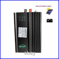
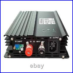
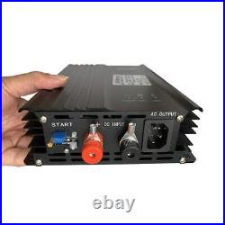
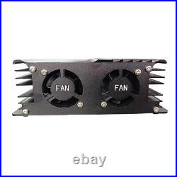
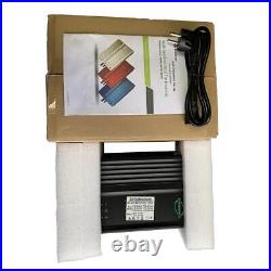

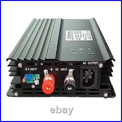
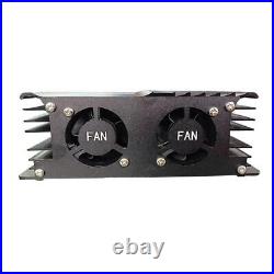
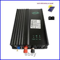
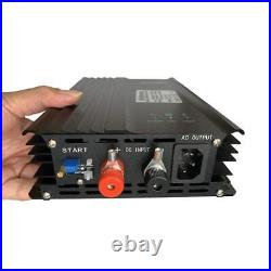
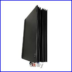
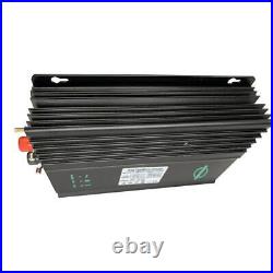
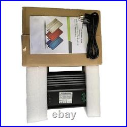
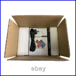
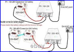
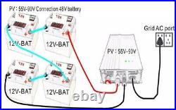
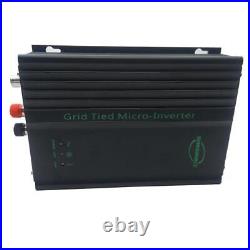
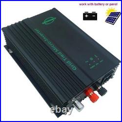
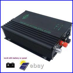
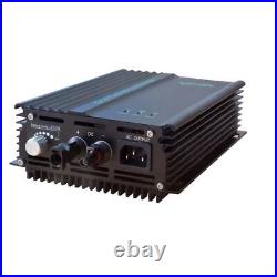
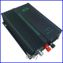
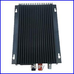
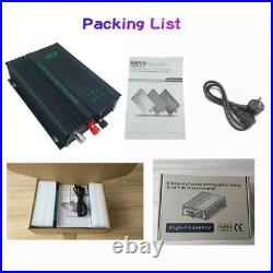

600W Micro Grid Tie Inverter for 24V – 96V Battery Adjustable output power MPPT. 600W MPPT Pure Sine Wave Micro Grid Tie Inverter 24V 48V Battery Discharge Adjustable to AC 110V or 220V MPPT Solar Panel Grid Tie Inverter CE The latest producted item (600ADJ)would be with new improved potentiometer and there would be no Aluminum fin heat sink for new produced 600W grid tie inverters but with two fans. (you may still receive old version before end Dec, 2022) Specifications. PV open voltage range. PV MAX input power(W). MPPT Voltage range(V). Suitable for Battery voltage(V). Battery Low Voltage Protection(V). PV mode AC MAX output (W). Battery mode Max output power. 220VAC(190-260VAC) or 120VAC(90-135VAC). 50Hz(4852) or 60Hz(5862). Stable real efficiency / 120V. Stable real efficiency / 220V. Islanding; Short-circuit; Low Voltage; Over Voltage; Over temperature Protection. Monocrystalline, polycrystalline, thin-film solar panels. 22.2×16.2×6.5CM. PV grid-connected inverter operating mode The grid-tied inverter has an automated working order, without needing to monitor. On detection the power output from solar panels, device will decide if the power was large enough to begin the conversion process. Coversion process includes 5 modes, Startup, Grid-tied begin, Standby, Stop, Fault-find. Startup – When the start button is on, solar panel and grid lines both connected in normal condition, inverter enters working condition. Grid-tied begin – Grid-tied begin mode is when inverter starts to convert the Direct Current fed through from PV solar panel to a stable Alternate Current and flow to the utility grid. To enable the maximum output of energy, the device uses MPPT control technology to track sun rays, this technology promises the maximum efficiency under diferent daylight and temperature conditions. Standby – Standby mode is when device detects insufficient power feeding through from the solar panel, or device detects abnormal status such as voltages, frequencies, and temperatures not in the permitted range, the device enters standby mode. Stop – Insufficient sunlight hence insufficient PV power feeding through to the device and device enters into the standby mode, when this condition continues and DC voltages falls below 12V for over 1 minute, the device will enter Stop mode. When error ocurs, fault find indicator starts flashing, device will enter Stop mode. Please see 3.4 error status on LED indicator. (Battery) discharge and grid mode(With ADJ function models) 1. The DC input of the system can be directly connected with the battery, Turn the knob of the inverter to the right into the battery mode, then the tracking function will be turned off, the output power will be adjusted from left to right, At this point the output power can be adjusted from 80W-450W or so arbitrary output to ensure that the inverter can work for a long time in the grid status. When the inverter connected to the battery discharge, if the battery voltage is too low, the inverter will automatically stop and cut off grid output to protect the battery over discharge to extend battery life. Different specifications of the input voltage of the inverter will be used with different voltage battery, the battery voltage protection point please refer to the following. Battery Low voltage protection. Battery high voltage protection. The product came very well packaged. I’m very happy. Thank you for everything.
